
You may also want to try visiting the Jumper
Wire 101 page for more information on this topic.
Both pages are similar. This one concentrates on
Experimental aircraft starter wiring scenarios. Between
the two pages, everything you never wanted to know about
aircraft starter wiring is covered.
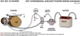
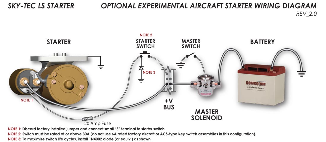
On experimental applications,
Sky-Tec LS, PM & HT starters may be wired to utilize the
starters' internal solenoid for use as the aircraft's starter
contactor per diagram "A"
below.
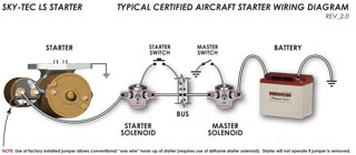
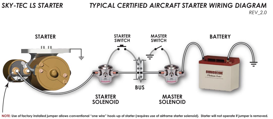
Nearly all known certified
applications require the use of a firewall starter contactor
and need to be wired according to diagram "B" below.
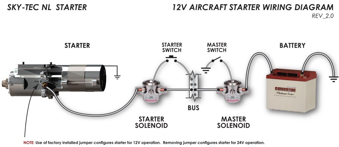
All Certified Sky-Tec NL starters must be
wired per diagram "B" below. On standard
certified NL (non /ec*) starters, there is no active
"S" terminal. The small, "S"
terminal on the standard NL model (non /ec*) starter is used to switch the starter
from 24V (jumper wire removed) to 12V (jumper wire installed)
operation and cannot be used to activate the starter in
certified aircraft applications that utilize a separate
starter contactor.
EXPERIMENTAL aircraft owners may rewire
the NL starter if they desire to eliminate the
aircraft's starter solenoid with the following caveats:
1) the push-to-start switch must be rated for 20A+, and 2) the
wire between the two should be equally appropriate in gauge.
Diagram
A
Experimental
Aircraft Wiring Diagram
Applicable to:
- Experimental aircraft
wishing to utilizing the starter's internal solenoid as
starter contactor
- Sky-Tec LS, PM or HT
starters
- Also: Sky-Tec HT
starters on Robinson Helicopters (Certified)
Diagram
B
Certified
Aircraft Wiring Diagram
For use with all certified
aircraft applications (except Robinson) and all NL starter
installations (certified AND experimental)
Applicable to:
- Certified aircraft with
firewall-mounted factory starter contactor
- Sky-Tec NL, LS, PM or HT
starters
- Also: Sky-Tec NL
starters on Experimental aircraft applications
| |
Diagram A
Experimental
Aircraft Wiring Diagrams
|
Diagram B
Certified
Aircraft Wiring Diagrams
|
| For
Lycoming
PM/LS Starters
|
Click to Enlarge Diagram
|
Click to Enlarge Diagram |
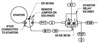
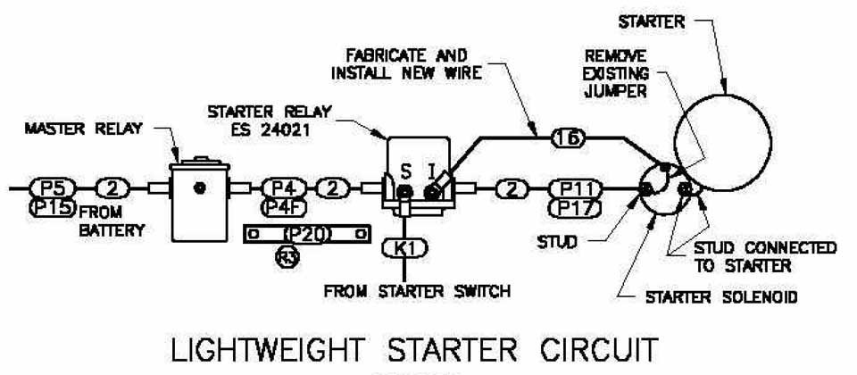
Van's
Aircraft
Diagrams
for
LS Starters |
RV-6, -7, -8, -9
Diagram
*** NOTE: THIS
IS A VAN'S AIRCRAFT WIRING DIAGRAM
SCANNED DIRECTLY
FROM VAN'S AIRCRAFT PLANS.
WE CAN NOT EXPLAIN WHY YOU WOULD WIRE YOUR
STARTER IN THIS MANNER. BUT IT WORKS FOR VANS.***
Click to Enlarge Diagram
NOTE: Van's
diagrams do NOT apply to Sky-Tec NL starters!
See NL Van's installation notes in NL section BELOW
|
With all due respect to
Van's,
Here's how we'd wire it if it were our RV and we were
using the supplied ACS keyswitch to start:
Click
to Enlarge Diagram
|
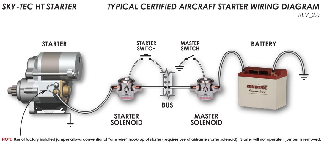
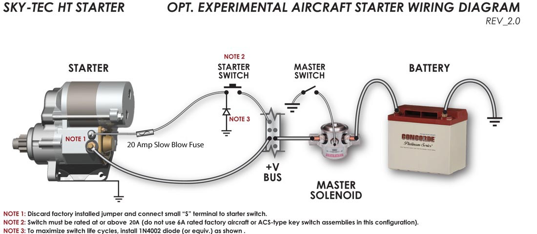
| For
Lycoming
HT
Starters
|

Click to Enlarge Diagram
|

Click to Enlarge Diagram
|
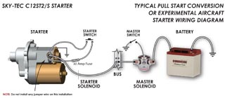
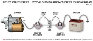
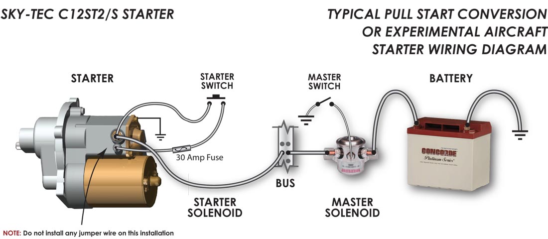
| For
Continental
C12ST2 Starters
|
NOTE: If installing the STC-certified
KCST2 / C12ST2/S pull-start conversion, do not refer to
these diagrams! Wiring instructions and diagrams
for the STC certified installation can be found on
the
ST2
Comprehensive Certification Page
Click to Enlarge Diagram
|
Click
to Enlarge Diagram
NOTE: Also
applicable to STC Certified Pull-Start conversion.
|


